PIC12F629 Led Chaser
A couple of weeks ago I completed a project where I made a homebrew CW keyer. When I first set out on that project I had intended to use a PIC12F629 microcontroller, but instead I ended up using an ATTINY85, and the (honestly excellent and feature complete) ATTiny85_CW_Keyer project. This keyer has worked great and I’m very happy with it, but I still had an appetite to do something with a PIC12F629. Why this microcontroller exactly? Well, mostly because I have a bunch of them that I bought a long time ago, I have a programmer for them, and they are INCREDIBLY basic. I mean really basic. The PIC12F629 has some impressive metrics, but impressive in probably all the wrong ways:
- no onboard ADC to speak of (Microchip makes the slightly pricier PIC12F675 that is basically the same chip, but with an ADC)
- approximately 2 kilowords of program memory (aka 2000 instructions or operands total)
- 1 comparator
- 6 GPIOs (using the Microchip tri state IO logic, so all 6 of those pins share functionality with other things)
- a whopping 128 whole bytes of EEPROM
So it’s a very basic chip and it makes even an Arduino Uno look like a complete powerhouse. But it does have one thing going for it (at least it did before the silicon shortage), it’s extremelly cheap. I picked up my units years ago, but they were less then 20 cents each back then. And, honestly, there’s something fun and novel about making a project with so few resources to work with. Getting the whole project to “fit” onto the chip is half the fun.
Since I still wanted to do something with a PIC12F629, I decided to set a little project goal for myself. Something small and achievable in a fairly short amount of time (weekend project), but a project where I could still learn a bit about programming for embedded systems with scarce resources. I decided to make an LED chaser. This chaser was to have 16 LEDs of output, the ability to vary the speed of display, and multiple patterns to display. Also I wanted it to be in a circle, since that seemed fun.
Since I wanted so many outputs, I knew I would have to turn to shift registers. Luckily I happened to have a bag full of 74HC595N serial in parallel out shift register ICs, so I decided the first step would be to make an LED chaser using two of those ICs and an Arduino. This seemed like an important step, since the Aruino is much easier to program then most PICs, and the ATmega328P is virtually a supercomputer compared to my little PIC. I figured it’d be easier to get a design in mind with this hardware, so I played around for an evening following this tutorial.
I got a board running this way (forgot to take pictures of this, sorry), and felt excited to now try my hand with the PIC. I set up the MicroLabX IDE and copy-pasted my Arduino code in there, finangled it a little bit to be proper mikroC, hit compile, and immediately found failure. A couple of systemic problems. One, I knew going in that I’d have to write a suitable replacement for the Arduino ‘shiftout’ built in function. This functionality obviously isn’t built into mikroC, so I’d need to make it myself. More importantly though, the main loop of my Arduino code was basically:
- have an array of byte arrays, each identifying a pattern to display on the LEDs
- grab two bytes from the selected byte array based on a for loop index, and shift those bytes out to the shift registers
- latch the shift registers to display what I shifted to them
- wait a determined amount of time
- grab the next two bytes, and repeat
My byte array was dynamically allocated as a global variable in my program (aka it was on the heap). This broke immediately when shifting to the PIC12F629. See memory is a resource, and my byte array was far exceeding what the PIC had to offer. Also, declaring global variables is part of your program code, and just defining the byte array of patterns to display was exceeding the PICs 2 kiloword instruction limit. I had to make my program much, much smaller!
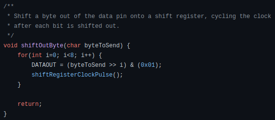
First things first, make a replacement for the shiftout function. The goal here was to make a function that could take a byte (or char) parameter (either a value or pointer, though I ended up just passing things by value), and then toggle a GPIO, in order, through that byte. I didn’t really care if I started with MSB or LSB, since I could change the hardware to match. Also, it needed to cycle the shift register clock pin while doing that. A complicated function, but easy with a bitmask.
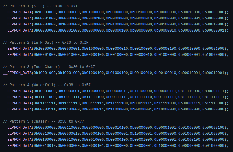
Now to worry about that memory problem. I figured that while I was clean out of program ROM and RAM, the PIC did have 128 bytes of EEPROM flash that I wasn’t using at that point. If I could preload that memory with my patterns, then I would just have to maintain an array of what registers in EEPROM each pattern started at and how long the pattern was, which would be far smaller then what I was currently storing. I found mikroCs __EEPROM_DATA function that initializes EEPROM to a known value, and proceeded to write out my patterns in this manner.
Then I refactored my program loop to basically be:
- Figure out what two bytes I should read from EEPROM
- Read those bytes and shift them out to the shift registers
- Latch the shift registers to display what I just wrote to them
- Iterate my local variables so that I can read the next two bytes from EEPROM
- Wait until I need to load the next two bytes
This worked great! I messed around with breadboarding out the circuit for a day or so, then made a schematic and set about making it on a perfboard. Videos of the finished board as well as some breadboard videos are below. Not a bad project, and it definitely scratched the itch of playing with a 20 cent microcontroller! If you’d like to view the code or build a unit for yourself, the code, a compiled hex file, and the full schematic are over on my GitHub.